Figure 1: Schematic Diagram of CR2032 Battery Case Components
As one of the most commonly used battery types in laboratories, button cells are widely applied in the fields of material development and electrochemical performance testing. This article will provide a detailed overview of the complete process for preparing button cell electrodes and assembling the batteries, including the required materials, equipment, steps, and precautions. This comprehensive guide aims to offer valuable insights for researchers in related fields.
A button cell consists of a set of button cell casings and internal components. Stainless steel battery casings are widely used in laboratory testing due to their excellent electrochemical stability, good sealing properties, small size, simple assembly, and low cost. Common models include CR2032,
CR2025, and CR2016, among which the CR2032 model (with a diameter of 20 mm and a thickness of 3.2 mm) is frequently used in laboratories. Additionally, there is a reusable Swagelok cell, which features a stainless steel outer casing and a polytetrafluoroethylene (PTFE) liner, making it suitable for battery disassembly and analysis.
A set of CR2032 battery casings includes: positive and negative electrode casings, springs, and gaskets. The basic steps for assembling a button cell include: slurry preparation, coating, drying, cutting, and assembly. The following sections will provide a detailed explanation using the CR2032 battery casing as an example.

Figure 1: Schematic Diagram of CR2032 Battery Case Components
(1) Material Mixing Process Selection Criteria
Decision-making on the process path using the quality threshold method:
Manual Grinding Method (0.1-5.0g range): Suitable for small quantities of active materials (e.g., initial screening of new electrode materials)
Mechanical Mixing Method (>5.0g): Achieving slurry homogenization through a laboratory mixer
(2) Coating Technology Compatibility Principle
Dynamic selection based on slurry volume:
Manual Coating: Conventional method (slurry volume <10mL), with controlled coating speed of 0.5-1.0mm/s
Mechanical Coating: Activate a small coating machine (slurry volume ≥10mL), with a blade gap precision of ±5μm
Electrode preparation involves two key stages: mixing and coating.
(1) Active Material: Generally in powder form for both positive and negative electrode materials, with particle size not too large (maximum particle diameter not exceeding 50μm for laboratory research, not exceeding 30μm for industrial applications). Grinding is required when particles are large and form aggregates.
(2) Conductive Agent: Commonly used carbon-based conductive agents such as acetylene black (AB), conductive carbon black, Super P, etc.
(3) Binder: Commonly used PVDF or PTFE systems, as well as SBR emulsion, etc.
(Typical mass ratio: Active Material: Conductive Agent: Binder = 8:1:1 (or 8:1.5:0.5, can be adjusted according to materials, but generally, the positive electrode material should not be less than 75%, and the conductive agent and binder should not be less than 5%)
(4) Solvent: Commonly used NMP (N-methyl-2-pyrrolidone).
Preparation of binder (PVDF) and solvent (NMP) solution: Three concentrations of 0.02g/mL, 0.025g/mL, and 0.03g/mL can be prepared, and the appropriate concentration for your material can be chosen. Mix the two substances in a wide-mouth bottle and magnetically stir until there is no white substance in the solution.
(Note: After preparation, the wide-mouth bottl、 should be sealed with parafilm because NMP is prone to absorbing moisture or deteriorating. It is important to first add the binder (such as PVDF) to the solvent NMP and stir at below 50℃ until the PVDF is completely dissolved.)

Figure 2: Mechanical Mixing and Manual Coating Process
(1) Prepare the solution: Add PVDF to NMP and stir until completely dissolved at a temperature below 50℃ until the solution is clear and transparent.
(2) Add conductive agent: Weigh out the conductive agent and slowly add it to the weighing bottle, stirring for 20 minutes.
(3) Add active material: Weigh out the active material and add it to the weighing bottle, stirring for 4-5 hours until the slurry reaches a viscous state.
(Note: During the process of adding the conductive agent and active material, try to avoid touching the side walls of the bottle as much as possible.)

Figure 3: Small Planetary Vacuum Mixer
(1) Selection of Current Collector: For lithium-ion battery electrodes, aluminum foil is used for the positive electrode and copper foil for the negative electrode. If the foil is smooth on one side, the coating should be applied to the rough side to increase the bonding strength between the current collector and the material.
(2) Coating Method: Use a doctor blade or a calendering coater for coating, ensuring that the material is flat and clean. Therefore, it is recommended to carefully clean the material and equipment with alcohol and lens cleaning paper before coating.

Figure 4: Automatic Film Coating Drying Machine
Electrode Drying:
(1) To remove a large amount of solvent NMP and water from the slurry, a combination of air drying and vacuum drying is necessary. Note that the baking temperature for NMP should be above 100℃. Under the premise of being able to dry, the baking temperature should be reduced and the baking time increased.
(2) During air drying, the maximum temperature can be set to 100℃ to remove moisture. However, since the moisture content is relatively low, the drying time can be shortened. During air drying, two temperature segments can be set, with different durations for each.
(Note: The drying temperature for the negative electrode should be lower than that for the positive electrode to prevent oxidation of the copper foil. Regarding the air drying temperature, the positive electrode should not exceed 120℃, and the negative electrode should not exceed 90℃. The time should also not be too long to avoid powder detachment.)
(3) After air drying, it is recommended to proceed with vacuum drying, typically set at a temperature of 120℃ for about 10 hours.
(Caution: Do not skip air drying and go directly to vacuum drying, as this can cause NMP to fill the vacuum drying chamber, affecting the drying effect. Air drying can also be used, but it requires a longer time.)
Calendaring Process: Use a roller press or a calendaring machine for calendaring. A roller press can generally compress the positive electrode coating to a thickness of 15~60μm. A calendaring machine can be used with a pressure of approximately 80~120kg/cm² for compression.

Figure 5: Electric Vertical Roller Machine
(1)Cutting: Use a punch press to cut out small electrodes, adjusting the diameter according to the battery case model.
(2)Weighing: Use a high-precision balance to weigh the mass of the electrodes and record the data.

Figure 6: Film Cutter
(1) Assembly Components: Negative electrode casing, lithium metal sheet, separator, gasket, spring sheet (nickel foam), positive electrode casing, electrolyte.
(2) Tools: Die for pressing electrodes, pipette, insulated tweezers.

Figure 7: Schematic Diagram of Button Cell Components
(1) Place the positive terminal case and gasket: Position the positive terminal case with the opening facing up, and place the gasket with the rough side facing down inside.
(2) Insert the positive electrode and saturate: Place the positive electrode with the coated side up in the center of the positive terminal case, and saturate it with electrolyte.
(3) Cover with a separator and saturate: Use tweezers to place the separator over the positive electrode, and saturate it again with electrolyte.
(4) Place the lithium sheet and gasket: Position the lithium sheet with the smooth side facing down, and align the gasket properly.
(5) Place the spring and negative terminal case: Align the spring properly, and cover with the negative terminal case.
(6) Seal the battery: Use a sealing machine to press and seal the battery, and check if the appearance is intact.
")
Figure 8: Button Cell Sealing Machine
Calculation Method for Active Material Mass:
Active material mass = (Electrode mass - Foil areal density * Electrode area) * Loading.
Resting Period: After the button cell is assembled, it needs to rest for 4 hours before testing (for some separators and electrolytes with poor saturation, the resting time needs to be increased).
Testing Procedures:
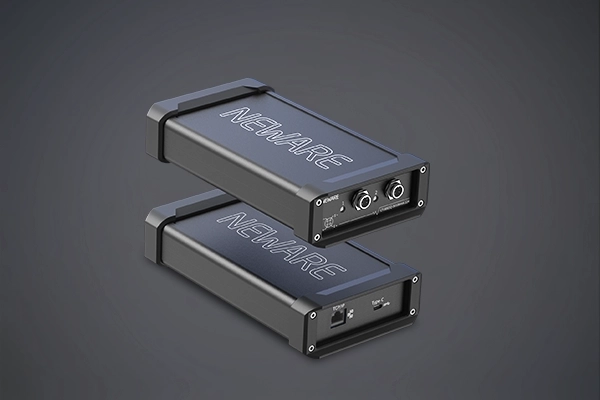
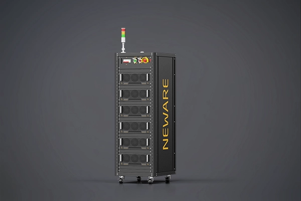
NEWAEW multi-channel battery testing system also integrates many working modes: (1) Charging modes: Constant current charging, constant voltage charging, constant current-constant voltage charging, constant power charging; (2) Discharging modes: Constant current discharging, constant voltage discharging, constant current-constant voltage discharging, constant power discharging, constant resistance discharging; (3) Direct current internal resistance (DCIR) testing; (4) Cycling test; (5) Nested cycling: With nested cycling function; (6) CT-8002S-5V100mA-124 supports CV (cyclic voltammetry) cycling test, with a maximum support of 3 levels of nesting.

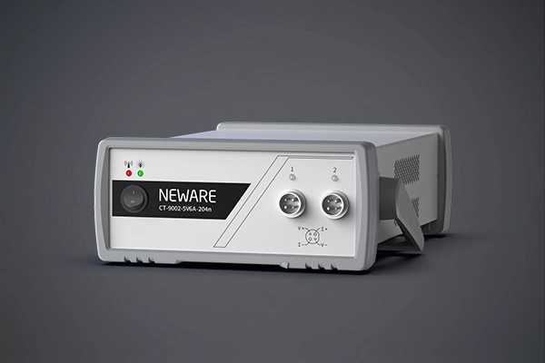
Figure 9: CT-4008Q-5V100mA-124 Battery Testing System

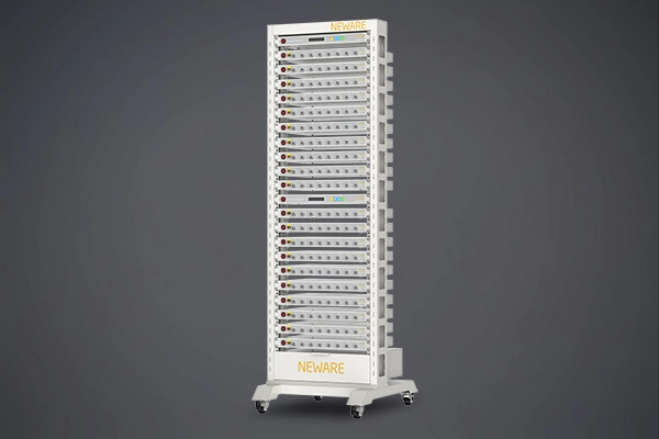
Figure 10: CT-8002S-5V100mA-124 Battery Testing System
Example 1: Setting the cycling performance test procedure for lithium-ion button cells
(1) Select the constant current cycling mode in the Sinwe BTS software.
(2) Test the assembled cells at a current density of 0.1 A/g within the corresponding voltage range. (Assuming the mass of the active material is 0.01g, the test current is 1mA)
(3) Set the positive electrode voltage range according to the electrode material (for example, the voltage range for testing lithium iron phosphate // Li cells can be set to 2~4.2V), which can be obtained by referring to literature or testing polarization curves.
(4) For the negative electrode material, the cells are generally subjected to a discharging process first, following the sequence of "rest-constant current discharge-constant current charge steps". Enter a current of 1mA, a discharge cutoff voltage of 0.01V, a charge cutoff voltage of 2.0V, and set the number of cycles to 2000.
The test voltage range in the following screenshot is for reference only; the specific voltage range should be determined based on the specific material.

Figure 11: Example of Cycling Procedure for Research on Lithium-Ion Button Cell Positive Electrode
Figure 12: Example of Cycling Procedure for Research on Lithium-Ion Button Cell Negative Electrode
Example 2: Setting the Rate Performance Test Procedure for Lithium-Ion Button Cells
(1) After allowing the battery to rest for 1 hour to stabilize its internal state, select the constant current rate mode in the Sinwe BTS software.
(2) Enter the theoretical specific capacity of the material and the mass of the active material to automatically calculate the current value for constant current charging and discharging. (For example, the theoretical specific capacity of lithium iron phosphate is 170mAh/g, with an active material mass set to 2mg).
(3) Set the rate gradients to 0.1C, 0.2C, 0.5C, 1C, 2C, 5C, 10C, 20C, and 1C.
(4) Refer to literature to obtain the voltage window of 2.0~4.2V, set the charge cutoff voltage to 4.2V, the discharge cutoff voltage to 2.0V, and cycle 10 times at each rate. After setting the test parameters, click start to begin.
(For detailed steps, you can watch the video below)
Example 3: Setting the Procedure for Galvanostatic Intermittent Titration Technique (GITT) Testing of Aqueous Zinc-Ion Button Cells
(1) Refer to literature to obtain a voltage window of 0.2V to 1.8V, and set the charging and discharging current density to 100 mA/g. (Assuming the active material mass is 1 mg, the current size is determined to be 0.1 mA based on the current density and active material mass)
(2) In the BTS software, select the channel and click "Single Point Start" to enter the procedure setting interface.
(3) The battery needs to rest for 1 minute before testing (the time can be adjusted as needed).
(4) Charging procedure:
Constant current charging for 5 minutes, rest for 5 minutes, at a current of 0.1 mA.Set protection conditions: If the charging voltage exceeds 1.8 V, proceed to the constant current discharging procedure.Rest condition: If the voltage does not reach 1.8 V and after resting for 5 minutes, return to the constant current charging procedure, and cycle through.
(5) Discharging procedure:
Constant current discharging for 5 minutes, relaxation for 5 minutes.
Set protection conditions: If the discharging voltage drops below 0.2 V, end the test.
Rest condition: If the voltage is above 0.2 V and after resting for 5 minutes, return to the constant current discharging procedure, and cycle through.
(6) The test can be ended or set to cycle through multiple GITT tests. Enter the active material mass, save, and then start the test.
(For detailed steps, you can watch the video below)
Example 4: Setting the Procedure for Deposition and Stripping Test of Aqueous Zn-Zn Symmetrical Cells
(1) Set the current size according to a current density of 1 mA/cm², taking an electrode with a diameter of 1 cm as an example, the current size is determined to be 0.785 mA based on the current density and electrode area.
(2) In the BTS software, select the channel and click "Single Point Start" to enter the procedure setting interface.
(3) Set the rest time to 1 minute, and set both charging and discharging times to 1 hour, with a current size of 0.785 mA.
(4) Set the cycling procedure, without knowing exactly how many cycles the symmetrical cell can undergo, it is recommended to set a higher number of cycles, and stop the test when the test voltage becomes chaotic. Save the procedure and the test will start.
(For detailed steps, you can watch the video below)
(1) Lithium Metal Sheets: Purity should not be less than 99.9%, and the diameter and thickness should be chosen according to requirements.
(2) Separator: Choose an insulating membrane with nano-pores, with dimensions larger than the lithium sheet and electrode.
(3) Electrolyte: Select according to experimental needs, and the amount used is generally in excess.
(1) Electrode Screening: The surface should be flat, with no obvious material loss, and the mass and thickness should be uniform.
(2) Battery Screening: The casing should be flat and undamaged, and the open-circuit voltage should be normal.
(1) Anti-Short Circuit: Use insulated tweezers to operate and avoid contact between the positive and negative electrodes.
(2) Cleaning and Drying: Assembled components need to be cleaned and dried to avoid contamination.
(3) Number of Assemblies: The number of batteries assembled with the same material should not be less than 5, considering errors and operational mistakes.
Sharp edges of electrodes piercing the separator, misalignment of positive and negative electrodes, loosely assembled batteries.
Insufficient addition of conductive agents, low porosity of the separator, decomposition of the electrolyte.
In summary, the preparation of button cell electrodes and battery assembly is a complex and delicate process that requires strict control of conditions and operations at every stage. It is hoped that this article will provide practical guidance and assistance to researchers, improving the efficiency of button cell preparation and testing.
NEWARE
47690 Westinghouse Dr, Fremont, CA 94539


● Voltage&Current Accuracy:±0.01% F.S.
● Recording Frequency:100Hz
● Current Response Time:≤1ms
● Minimum Pulse Width:500ms
● Off-Line Test:1GB/CH
● Cycle Life, GITT Test, DCIR Test, dQ/dV Curve
● Voltage & Current Accuracy:±0.01% F.S.
● Recording Frequency:10Hz
● Sampling Time:100ms
● Current Response Time:≤1ms
● Minimum Pulse Width:500ms
● Off-Line Test: 1GB
● Voltage & Current Accuracy:±0.05% F.S.
● Recording Frequency:10Hz
● Sampling Time:100ms
● Current Response Time:≤1ms
● Energy Efficiency:>65%
● Off-Line Test: 1GB
● Voltage & Current Accuracy:±0.05% F.S.
● Recording Frequency:10Hz
● Sampling Time:100ms
● Current Response Time:≤1ms
● Energy Efficiency:>65%
● Off-Line Test: 1GB
● Voltage & Current Accuracy:±0.05% F.S.
● Recording Frequency:10Hz
● Sampling Time:100ms
● Current Response Time:≤1ms
● Energy Efficiency:>65%
● Off-Line Test: 1GB
● Voltage Accuracy:±0.02% F.S.
● Current Accuracy:±0.05% F.S.
● Resolution Ratio AD/DA:16bit
● Current Response Time:≤1ms
● Minimum Pulse Width:100ms
● Off-Line Test:1GB/CH
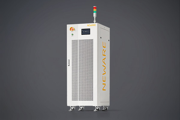
● Voltage & Current Accuracy:±0.05% F.S.
● Recording Frequency:100Hz
● Current Conversion Time:≤6ms
● Current Response Time:≤3ms
● Minimum Pulse Width:100ms
● Feedback Efficiency (Max) :75%
● Voltage & Current Accuracy:±0.02% F.S.
● Voltage & Current Stability:±0.01% F.S.
● Recording Frequency:1000Hz
● Resolution AD:16bit
● Current Response Time:≤100μs
● Off-Line Test: 1GB