During the charge and discharge process of lithium-ion batteries, multiple electrochemical reaction processes occur, which affect the structural morphology of the electrode materials and the performance of the battery. For instance, the specific capacity and discharge platform of the electrode materials determine the energy density of the battery, while the impedance of the materials or the battery itself determines the ion diffusion process and the power density of the battery. Common electrochemical testing techniques such as cyclic voltammetry, electrochemical impedance, and charge-discharge testing are used to study the electrochemical reaction processes and the cycling performance of electrochemical energy storage devices like lithium-ion batteries.
Cyclic voltammetry (CV)
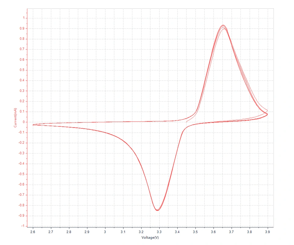
The principle of Cyclic Voltammetry testing
In the electroanalytical techniques for lithium-ion batteries, Cyclic Voltammetry (CV) is a widely used method by electrochemists. This method involves applying a linearly varying voltage (with a constant scan rate) to an electrode. The scanning range can be controlled within ±3 V of the resting potential, where most electrode reactions occur, and generally does not exceed ±5 V.
In Cyclic Voltammetry, the initial scan potential can be represented as
E = Ei − vt
In the formula: Ei - tinitial potential, t - time, v - potential change rate or scan rate. The reverse scan cycle is defined as
E = Ei + v′
where v' is often the same as v,and combining it with the appropriate form of the Nernst equation allows one to derive an expression that describes the flux of particles at the electrode surface, which can be solved by integrating the sum of continuous small steps.
In electrochemistry, particularly in the application of cyclic voltammetry, the peak current of reversible reduction typically refers to the current value corresponding to the maximum rate of the reduction reaction during the potential scan process. This peak current can provide information about the reversibility of the electrode reaction. For a reversible electrochemical reaction, the sizes of the oxidation peak and reduction peak currents should be approximately equal, and the peak potential difference should also be close to the theoretical value predicted by the Nernst equation, which is usually 59/n mV at room temperature for a single electron transfer reaction, where n is the number of electrons involved in the reaction.
The Randles-Sevcik equation can be used to describe the relationship between the peak current and the scan rate, and its formula is:
Equation 3 Randles-Sevcik equation
Where ip is the peak current, A is the working electrode area, n is the number of electrons transferred, F is the Faraday constant, C0 is the concentration of the electroactive species in solution, v is the scan rate, and D is the diffusion coefficient of the substance. The peak current is directly proportional to the square root of the scan rate, which can be used to determine the diffusion coefficient of the electroactive species.
Cyclic voltammetry can provide qualitative and quantitative information about the electrode process, and under the control of diffusion, a pair of nearly symmetrical current peaks appears in the reversible reaction. The peak potential difference is:
Equation 4 Peak potential difference
The potential difference is independent of the scan rate. In the case of reversible oxidation of an insoluble film for electrodeposition, if the process is not diffusion-controlled, the ΔE value will be much smaller than the value given by Equation (4).
For quasi-reversible processes, the current peaks will be more separated, with peak shapes closer to a semi-circle, and the peak potential will be dependent on the scan rate, resulting in a ΔE value greater than that given by Equation (4). Regression analysis of the relationship between Em and the scan rate v can also yield α and k, but using Equation (5) for analysis is much more convenient.
Equation 5
The principle of Linear Sweep Voltammetry (LSV) is similar to that of Cyclic Voltammetry and is often used to determine the reversibility of electrode processes and investigate the adsorption/desorption of active species on electrodes, with the key difference of lacking the reverse scan as compared to Cyclic Voltammetry. LSV is the most commonly used experimental technique in electrochemistry and a primary method for electrochemical characterization. For reversible electrode reactions, the peak potential Ep is independent of the scan rate v. However, in the case of an irreversible electrode reaction (quasi-reversible or completely irreversible), the peak potential shifts negatively (or positively) with increasing scan rate.
Formula 6 The peak potential formula related to reversible electrode reactions in electrochemistry
The testing method and steps of cyclic voltammetry(CV)
For assembled pouch or cylindrical lithium-ion batteries, their CV or LSV curves can typically be directly tested using an electrochemical workstation. Initially, the green clamp of the electrochemical workstation is attached to one side of the assembled battery's working electrode, while the red clamp (counter electrode) and the white clamp (reference electrode) are attached to the opposite pole of the battery. Then, the CV test function is selected to enter the parameter settings. The parameters to be set include initial potential, upper limit potential, lower limit potential, end potential, initial scan direction, scan rate, number of scan segments (2 segments make a full cycle), sampling interval, rest time, instrument sensitivity, working mode, etc. The voltage is scanned from the initial potential to the upper limit potential and then to the lower limit potential. The slope of voltage against time represents the scan rate, eventually forming a closed curve, indicating the redox reactions occurring at the electrode in the electrochemical system. For the negative electrode material, the initial potential is generally set as the upper limit potential, scanning from high to low potential and finally back to high potential. The procedure is reversed for the positive electrode material. The LSV testing steps and methods are similar to CV testing, with the key difference being the absence of a reverse scan, involving only the initial and end potentials.
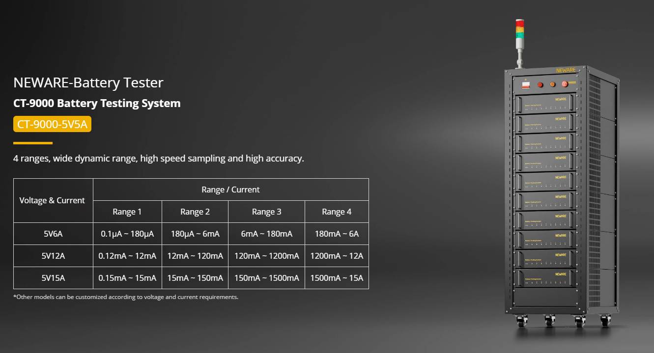
NEWARE CT-9000-5V5A Battery Testing System supports cyclic voltammetry (CV) testing for batteries
Electrochemical impedance spectroscopy (EIS)
The testing principle of Electrochemical Impedance Spectroscopy (EIS)
The positive electrode of a lithium-ion battery has a high voltage, serving not only as an electrode material participating in electrochemical reactions but also as a source of lithium ions for the battery. The negative electrode, with lower voltage, acts to store lithium ions during battery charging and releases them during discharge, facilitating a reversible lithium-ion deintercalation/intercalation process. Thus, important characteristics of lithium-ion battery electrodes, such as charge/discharge capacity, cycling stability, and rate capability, are closely related to the extraction and insertion processes of lithium ions in the intercalation electrode materials. These processes can be effectively revealed through the measurement and analysis of electrochemical impedance spectroscopy (EIS).
By likening the electrode processes in the battery to a simple circuit composed of resistors and capacitors in series or parallel, disturbance signals are inputted by the electrochemical workstation testing equipment, producing corresponding output signals. By analyzing the measured electrochemical impedance spectroscopy (EIS) spectra, the equivalent circuit or mathematical model of EIS can be determined. When combined with other electrochemical methods, the dynamics and mechanisms within the battery can be inferred. Applying small-amplitude sinusoidal waves to polarize the electrodes does not significantly induce concentration polarization or alter surface states. The disturbance and system response exhibit an approximately linear relationship, allowing processes at different rates to be easily separated in the frequency domain.
Impedance spectra are obtained over a wide frequency range to determine the number of sub-processes involved, leading to discussions on dynamic characteristics. Consequently, EIS can provide more information about electrode process kinetics and electrode interface structure compared to conventional electrochemical methods.
Currently, the main models describing the electrochemical insertion reaction mechanism are the adsorption model and the surface layer model. Generally, the surface layer model is used to describe the extraction and insertion processes of lithium ions in intercalation electrodes. The surface layer model was initially proposed by Thomas et al., dividing the model into high-frequency, mid-frequency, and low-frequency regions, gradually refining it. Barsoukov, based on the analysis of the insertion and deintercalation processes of lithium ions in individual active material particles, presented a micrographic model diagram of the insertion and deintercalation processes of lithium ions in intercalation electrodes (refer to Figure 1). It is believed that the extraction and insertion processes of lithium ions in intercalation electrodes involve the following steps:
Transport of electrons between active material particles and transport of lithium ions in the electrolyte between active material particle interstices.
Diffusion and migration of lithium ions through the solid electrolyte interface (SEI) layer on the surface of active material particles.
Charge transfer process at the electron/ion conducting interface.
Solid-state diffusion process of lithium ions within active material particles.
Accumulation and consumption of lithium ions in the active material, leading to changes in the crystal structure of active material particles or the formation of new phases.
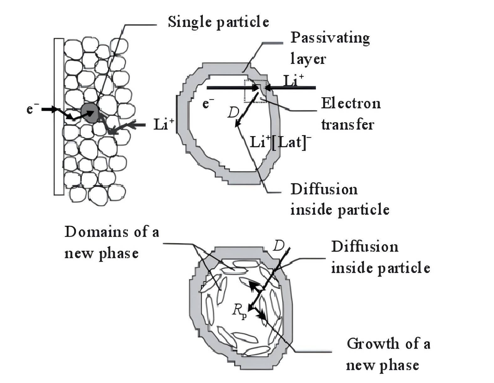
Figure 1 A diagram illustrating the mechanistic model of lithium intercalation in the electrode
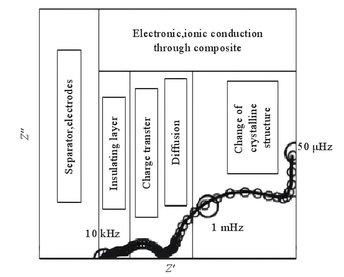
Figure 2 The typical electrochemical impedance spectrum of lithium ions' extraction and intercalation in composite electrodes
Taking into account the influence of conductive agents on the insertion and extraction of lithium ions, that is, the impact of electron transport processes on the lithium insertion process, researchers have enhanced the surface layer model. The typical electrochemical impedance spectra of the extraction and insertion processes of lithium ions in intercalation electrodes are divided into five parts, as shown in Figure 2. However, due to experimental constraints, it is difficult to observe the semicircle associated with changes in the crystal structure of active material particles or the formation of new phases in the extremely low-frequency region (<0.01 Hz), as well as the vertical line related to the accumulation and consumption of lithium ions in the active material.
A typical EIS spectrum is mainly composed of 4 parts:
High-frequency region: A semicircle associated with the diffusion and migration of lithium ions through the solid electrolyte interface (SEI) layer on the surface of active material particles.
Mid-high-frequency region: A semicircle related to the transport of electrons within the active material particles.
Mid-frequency region: A semicircle associated with the charge transfer process.
Low-frequency region: A sloping line related to the solid-state diffusion process of lithium ions within the active material particles.
The high-frequency region of the electrode EIS spectrum is a semicircle related to the diffusion and migration of lithium ions through the solid electrolyte interface (SEI) layer on the surface of active material particles (high-frequency region semicircle), which can be represented by a parallel circuit RSEI/CSEI. RSEI and CSEI are fundamental parameters characterizing the diffusion and migration process of lithium ions on the surface of active material particles through the SEI layer. Understanding the relationship between RSEI, CSEI, and the thickness, time, and temperature of the SEI layer is essential for applying EIS to study the diffusion process of lithium ions through the SEI layer on the surface of active material particles. By observing changes in RSEI and CSEI, the formation and growth of the SEI layer can be predicted.
The mid-high-frequency region is a semicircle related to the transport process of electrons within the active material particles, which can be represented by a parallel circuit Re/Ce. Re represents the electronic resistance of the active material, a fundamental parameter characterizing the transport process of electrons within the active material particles. Changes in Re with the electrode polarization potential or temperature reflect variations in material conductivity with electrode potential or temperature. Essentially, the semicircle in the mid-high-frequency region of the intercalation electrode EIS spectrum is related to the electronic conductivity of the active material.
In practical intercalation electrode EIS spectra, the mid-frequency region is characterized by a semicircle related to the charge transfer process, which can be represented by a parallel circuit of Rct/Cdl. Rct and Cdl are fundamental parameters that characterize the charge transfer process.
The low-frequency region is represented by a straight line associated with the diffusion process, which can be expressed using a Warburg impedance Zw. Zw characterizes the solid-state diffusion process of lithium ions within the active material particles, and the corresponding diffusion coefficient of lithium ions within the active material particles of the intercalation electrode is a key kinetic parameter that characterizes the diffusion process.
The extremely low-frequency region (<0.01 Hz) consists of a semicircle associated with changes in the crystal structure of active material or the formation of new phases, along with a vertical line related to the accumulation and consumption of lithium ions within the active material. This process can be represented by a parallel circuit of Rb/Cb and a series circuit composed of Cint, where Rb and Cb represent the resistance and capacitance characterizing the intrinsic structural changes of the active material particles. Due to the frequency range of EIS typically being 10^-2 to 10^5 Hz and the minimal volume changes during the lithium ion insertion and extraction processes in the positive or negative electrode materials of lithium batteries, as well as the limited physical and chemical property variations within the bulk phase and the absence of significant phase transition processes, and the relatively minor differences in physical and chemical properties between newly formed phases and original phases, it is challenging to observe the extremely low-frequency region in EIS spectra. This region, associated with changes in the crystal structure of active material particles or the formation of new phases, is often not easily observable.
For graphite negative electrodes and other carbon electrodes, the active material serves as a good conductor for electrons, leading to a very small electronic resistance (Re). Therefore, their EIS spectra do not contain a semicircle associated with the Re/Ce parallel circuit. In this case, the EIS spectrum is composed of three parts: two semicircles related to parallel circuits of RSEI/CSEI and Rct/Cdl, and a sloping line reflecting the solid-state diffusion process of lithium ions.
For transition metal oxides or transition metal phosphates as positive electrodes, theoretically, their EIS spectra should consist of the four parts described earlier. However, due to the coupled processes of lithium ion diffusion and migration through the solid electrolyte interface (SEI) layer on the surface of active material particles and the transport of electrons within the active material particles, the two semicircles associated with Re/Ce and RSEI/CSEI parallel circuits tend to overlap, appearing as a single semicircle in the EIS spectrum. Literature reports suggest that their EIS spectra typically consist of two semicircles or three semicircles along with a sloping line, with the combination of two semicircles and a sloping line being the most common observation.
Method and steps of electrochemical impedance spectroscopy (EIS) testing
To conduct electrochemical impedance testing, there are three fundamental conditions:
Causality condition: When perturbing the electrode system with a sinusoidal potential signal, the causality condition requires that the electrode system responds only to that potential signal.
Linearity condition: The change in a state variable must be small enough to linearly approximate the relationship between the change in the electrode process rate and that state variable.
Stability condition: After perturbations cease, the electrode system should return to its initial state, often related to the internal structure of the electrode system, i.e., the dynamic characteristics of the electrode process.
Electrochemical impedance testing on lithium-ion batteries is generally carried out using an electrochemical workstation. Commonly used workstations include CHI Electrochemical Workstation and Zahner Electrochemical Workstation. This article uses Zahner as an example to introduce the EIS testing process.
Firstly, access the EIS mode, enter the parameter setting interface, choose different modes for impedance testing, set the frequency range, start frequency point, frequency test order, sampling interval, etc., and obtain the test results.
To obtain reliable results from EIS, fitting the impedance spectrum to an equivalent electrical circuit (EEC) is crucial. Start by opening the impedance spectrum that needs fitting, where you can modify the line's color, thickness, format, etc. Choose the Nyquist plot representation, then click the "Model Circuit" icon to create an equivalent circuit model. Add the required circuit components by clicking "Add" and connect them through connection points, providing a frequency range to generate a simulation plot. After simulating, open the simulation plot in the graph window. To fit the simulated curve to the measured EIS impedance spectrum, you have three simulation options: Original, Smoothed, and Z-HIT. Choose the desired option and click "Fit" to perform the fitting. After fitting, impedance values and errors for each component will be provided. Lastly, save and export the fitting data. Common fitting software includes Zsimpwin and ZahnerAnalysis.
Principles of charge and discharge testing
Comprehensively testing and evaluating the capabilities of lithium-ion batteries is crucial for developing safe and reliable lithium-ion batteries for new energy vehicles and consumer electronic products. Therefore, there are higher requirements for standardizing and making the testing methods of lithium-ion batteries more comprehensive. Charge and discharge testing, as the most direct and common testing and analysis method, can be used to test various characteristics of materials such as capacity, Coulombic efficiency, overpotential, rate capability, cycling performance, high and low-temperature characteristics, voltage curve characteristics, among others.
The current charge and discharge testing instruments have multiple testing functions and can perform multi-channel charge and discharge testing simultaneously. The main function of battery charge and discharge testing instruments is to carry out the processes of charging and discharging. The choice of charge and discharge methods for lithium-ion batteries directly impacts the battery's lifespan. Selecting appropriate charge and discharge methods can not only extend the lifespan of lithium-ion batteries but also improve their utilization. Common charge and discharge modes for pouch batteries include constant current charging, constant voltage charging, constant current discharging, constant resistance discharging, hybrid charge and discharge, and stepwise charge and discharge.
In the laboratory setting, constant current charging (CC), constant current-constant voltage charging (CC-CV), constant voltage charging (CV), and constant current discharging (DC) are commonly used to test the charge and discharge behavior of batteries. Among these, constant current-constant voltage charging is the most widely used method, as it combines constant current charging and constant voltage charging. The charging process can be divided into three stages: pre-charging stage, constant current charging stage, and constant voltage charging stage. The pre-charging stage is necessary when the battery voltage is below 3 V, as the battery cannot withstand high current charging at this point. When the battery voltage reaches 3 V, it can handle high current charging, which should be done at a constant high current to ensure rapid and uniform transfer of lithium ions. As the voltage reaches 4.2 V, the battery is at its voltage limit and should be charged at a constant 4.2 V voltage, gradually reducing the charging current. When the charging current drops below 30 mA, the battery is fully charged, and charging should be stopped to avoid reducing the battery's lifespan due to overcharging.
Moreover, overcharging and over-discharging of lithium-ion batteries can cause permanent damage to the positive and negative electrodes. Over-discharging leads to collapse in the structure of the negative electrode carbon layer, preventing lithium ions from being inserted during the charging process. Overcharging results in an excess of lithium ions embedding into the negative electrode carbon structure, causing some of these ions to be unable to be released. Therefore, the optimal charge and discharge method to maintain the best performance of lithium-ion batteries is shallow charging and discharging.
The magnitude of charge and discharge currents is typically expressed in terms of charge and discharge rates, that is: Charge/Discharge Rate (C) = Charge/Discharge Current (mA) / Rated Capacity (mAh). For example, if a battery with a rated capacity of 1,000 mAh is charged or discharged at a current of 100 mA, the charge/discharge rate would be 0.1C. Laboratory testing of lithium-ion pouch batteries commonly includes charge/discharge cycle testing, rate capability testing, and high/low-temperature charge/discharge testing.
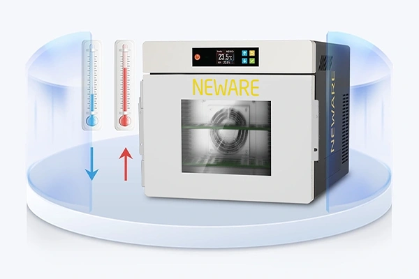
During laboratory testing of lithium batteries, temperature cycling chambers and constant temperature boxes are often utilized. The temperature control in laboratory constant temperature boxes is typically set at 25°C, with an actual temperature variance of no more than 1°C from the set temperature. Temperature cycling chambers are used to test the high and low-temperature performance of batteries by setting specific temperatures. When selecting a constant temperature box, it is advisable to choose one specifically designed for battery testing, as these boxes come equipped with professional insulation and thermal ports for connecting battery test leads. When connecting batteries to test fixtures, insulated tweezers should be used, and the test batteries should be neatly placed inside the temperature cycling chambers or constant temperature boxes. The testing temperature should be set, and the battery testing program should be initiated once the temperature reaches the set value.
Summary
Cyclic voltammetry, AC impedance, and charge/discharge testing are widely used electrochemical testing techniques in lithium-ion battery research. By analyzing cyclic voltammetry curves, information such as redox reaction potential, ion diffusion coefficients, pseudo-capacitance, and more can be obtained. Fitting electrochemical impedance spectroscopy data can provide insights into electrolyte resistance, electrode/electrolyte interface impedance, charge density, and other parameters. Charge/discharge testing helps in obtaining battery capacity, charge/discharge platforms, and other crucial information, playing a significant role in studying electrode reaction processes and battery performance degradation mechanisms.
It is important to note that while the underlying principles of the same electrochemical testing techniques are similar, variations in testing instruments, methods, and analysis approaches can significantly impact the test data. Therefore, it is essential to establish and standardize testing protocols, develop robust testing and analysis methods to acquire reliable and accurate data. Furthermore, enhancing in-situ testing techniques, especially for electrochemical impedance testing, can enable real-time dynamic observation of battery information in different operational states, facilitating a deeper analysis of electrochemical reaction mechanisms.
To delve deeper into understanding battery degradation mechanisms, besides utilizing these electrochemical testing techniques, it is beneficial to combine them with other physicochemical testing techniques such as in-situ XRD (X-ray diffraction), XPS (X-ray photoelectron spectroscopy), etc., to reveal the inherent relationships between electrochemical information and material composition, structure, morphology, and other physicochemical characteristics.
Undoubtedly, establishing a comprehensive database tailored for different battery systems, encompassing key battery materials, physicochemical, and electrochemical information, will effectively guide the research and development of secondary batteries. In the current era of rapid advancements in energy storage technologies and big data analytics, such an initiative is increasingly imperative.


