Under the double pressure of environmental pollution and energy crisis, energy saving and emission reduction have become the common responsibility of all countries in the world. Against this background, new energy vehicles using clean energy are developing rapidly around the world. Lithium-ion batteries are widely used in various electronic devices and electric vehicles due to their outstanding advantages in energy density, cycle life and environmental performance. However, their potential safety hazards cannot be ignored. In order to ensure the safety of lithium-ion batteries, a series of rigorous safety tests must be conducted. In this paper, we will introduce the short-circuit test of lithium-ion batteries, and discuss its test methods, evaluation criteria and its impact on battery safety.
Internal short circuit is considered to be one of the most important causes of thermal runaway, fire and even explosion of Li-ion batteries. The triggers and mechanisms of internal short circuit are usually related to manufacturing defects within the battery, mechanical damage during use, material aging, thermal runaway and other factors.
Internal short circuit refers to the direct connection between positive and negative electrodes through electrolyte inside the battery, leading to battery failure or thermal runaway. Internal defects are mainly divided into two categories: structural deformation during the manufacturing process and manufacturing-induced defects. Structural deformation mainly occurs in the battery diaphragm and electrode, such as diaphragm defects. The diaphragm is an insulating material located between the positive and negative electrodes, and if perforations, uneven thickness and other defects occur during the manufacturing process, it may lead to direct contact between the positive and negative electrodes, triggering an internal short circuit. During the manufacturing process of lithium-ion battery production, unregulated operating environment may lead foreign objects into the battery interior. Research shows that the electrode material in the manufacturing process, if there are foreign objects (such as metal particles, etc.) or uneven distribution of materials, may also pierce the diaphragm leading to internal short circuit. External shock: Battery subjected to mechanical shock or extrusion, may lead to internal structure damage, diaphragm rupture, triggering an internal short circuit.
Electric vehicles will inevitably experience collisions during daily use. When the collision occurs, the strong external force will cause the battery deformation and displacement, known as mechanical abuse, mechanical abuse mainly includes extrusion and puncture, mechanical abuse occurs, will make the battery diaphragm puncture or failure, triggering an internal short circuit, which will lead to thermal runaway and fire in serious cases.Sharp objects penetrate into the battery, directly piercing the diaphragm and causing a short circuit.
Electrical abuse is one of the most common safety hazards of lithium-ion batteries during use, and overcharging and over-discharging are the main factors leading to electrical abuse. Literature studies have shown that overcharging can cause lithium dendrites to form on the surface of the negative electrode when the battery is overcharged or charged at low temperatures, and these dendrites will gradually penetrate the diaphragm and come into contact with the positive electrode, triggering an internal short circuit. Overcharging or discharging of the battery leads to an increase in the internal temperature of the battery, and the decomposition of the electrolyte generates gases, leading to the melting or rupture of the diaphragm and triggering a short circuit.
High temperature is the most common cause of thermal abuse of lithium-ion batteries lithium-ion batteries working temperature range is narrow, heat resistance is poor, if prolonged work in a high-temperature environment, it will bring irreversible damage, and in serious cases, may also be on fire, explosion and other dangerous accidents. Self-heating of the battery in a high temperature environment may lead to melting of the diaphragm and contact between positive and negative electrodes. Certain positive materials (such as high nickel ternary materials) will expand during the charging and discharging process, and long-term cycling may lead to damage to the diaphragm and the formation of an internal short circuit.
Using high precision internal short circuit inducer to ensure controllable short circuit location and conditions. Adopt memory metal alloy to be made into trigger element, use its memory property to keep the surface flat at room temperature and implant it into the battery sample, when the temperature rises the tip of the trigger element warps and pierces the diaphragm, realizing the low-resistance short-circuiting between the positive portion of the battery interior (including the positive electrode lugs, the positive collector, and the positive active substance) and the negative portion of the battery (including the negative electrode lugs, the negative collector, and the negative active substance). Internal short circuit testing is typically performed by introducing metal particles or other conductive materials inside the battery to simulate a short circuit within the battery.
Steps:
Prepare the battery to be tested and record its initial state.
Use an internal short circuit inducer to introduce a source of short circuit inside the battery.
Monitor battery voltage, temperature and appearance changes and record relevant data.
Based on the test results, the internal short-circuit safety of the battery is evaluated.
The test results were processed as follows.
a) Calculate the time elapsed from the trigger of the internal short-circuit to the first voltage drop of more than 100 mV in the battery sample according to Equation (1).
ΔT = T2 - T1 (1)
Where: T1 - the moment when the voltage starts to drop, s;T2 - the moment when the voltage of the battery sample drops for the first time over 100 mV, s;
b) Calculate the value of voltage change of the battery sample from the trigger of internal short circuit to the moment of termination of the test, according to formula (2).
ΔU = UE - U1 (2)
Where: U1 - voltage of the battery sample at the moment of short-circuit triggering in the battery sample, V;UE - voltage of the battery sample at the moment of the end of the test, V.
c) Calculate the value of temperature rise caused by short-circuit triggering within the battery sample according to Equation (3).
Δt = tM - t1 (3)
Where: t1 - temperature at the moment of short-circuit triggering within the battery sample, ℃: tM - maximum value of battery temperature, ℃.
The maximum temperature of different SOC cells versus displacement is shown in Fig. 3. After loading, the cell temperature increases rapidly in a short period of time.The temperature curves for 60% SOC, 80% SOC and 100% SOC are approximately vertically upward.The maximum cell temperatures corresponding to 0% SOC, 20% SOC, 40% SOC, 60% SOC, 80% SOC and 100% SOC are 35.48, 124.32, 129.07, 372.16 , 470.07 and 444.18°C, respectively. The average temperature rise rates are 0.54 °C/s, 2.10 °C/s, 2.45 °C/s, 21.92 °C/s, 37.39 °C/s and 52.85 °C/s. It can be seen that the rate of maximum temperature rise is positively correlated with the state of charge after the battery undergoes an internal short-circuit, and the dependence of the maximum temperature on the state of charge is very specific, and the maximum temperature of the battery increases with the increase of SOC.
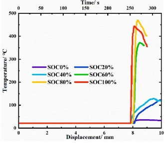
Fig. 1 Temperature-displacement curves for different soc cells
External short circuit is one of the most likely failures in power battery safety accidents, and it is also one of the important reasons for triggering the thermal runaway of the battery. External short-circuit occurs instantly will produce a high current discharge, the battery internal will occur a series of electrochemical reactions, which in turn cause a series of chain exothermic reaction, and ultimately triggered the battery temperature rises sharply, coupled with the electrical abuse and thermal abuse of the situation.
An external short circuit is a direct connection between the positive and negative terminals of a battery on the outside, resulting in a high current passing through the battery, which causes the battery to overheat, fail or even explode. The formation mechanism of external short circuit mainly includes the accidental contact of external conductive objects, such as metal tools and other conductive objects accidentally contact the positive and negative terminals of the battery, forming a short circuit. This situation is common in the maintenance or use process, did not notice the battery's positive and negative terminals exposed. Connection error is also a common cause, in the process of experimentation or use, incorrectly connected to the positive and negative terminals of the battery, such as misconnecting the electrodes, resulting in a short circuit, which is usually due to improper operation or unclear labeling. In addition, internal connection failures in the battery pack, such as failure of the cells or connecting wires, can also lead to shorting of the positive and negative terminals, and failure of the battery protection circuits (e.g., overcurrent protection) to cut off the circuits in time in case of an external short-circuit, which further exacerbates the risk of a short-circuit. External environmental factors such as batteries exposed to humid environments or soaked in water, resulting in shorting of the positive and negative terminals through the water medium, can also trigger an external short circuit. In addition, conductive contaminants (e.g. salt) on the surface of the battery may also trigger a short circuit. These environmental factors are not easily detectable in actual use, but may pose a serious threat to battery safety. By understanding these formation mechanisms, the risk of external short circuits in lithium-ion batteries can be better prevented and managed to ensure battery safety.
Use the battery short-circuit tester, stipulate the test ambient temperature 25℃ as one of the test conditions, the external circuit resistance of the external short-circuit is not more than 5mΩ.Drawing on GB/T31467.3-2015, it is stipulated that the external circuit is turned on and kept on for 10min, and is observed for 1h after the end of the test.The external short-circuit test is simulated by connecting a low impedance wire between the positive and negative electrodes of the battery directly to simulate the situation of an external short-circuit.
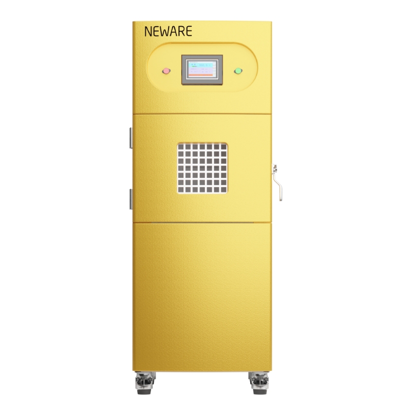
Figure 2 Battery short circuit tester
Steps:
Prepare the battery to be tested and record its initial state.
Start the short circuit test by connecting the positive and negative terminals of the battery using a low impedance shorting device.
Monitor battery voltage, temperature and appearance changes and record relevant data.
Based on the test results, the battery's external short-circuit safety is evaluated.
The 18650-type cylindrical battery monoblocks were tested at 50% ambient humidity, -10°C, 10°C, 25°C and 40°C ambient temperatures, and the test results are shown in Fig. 3.
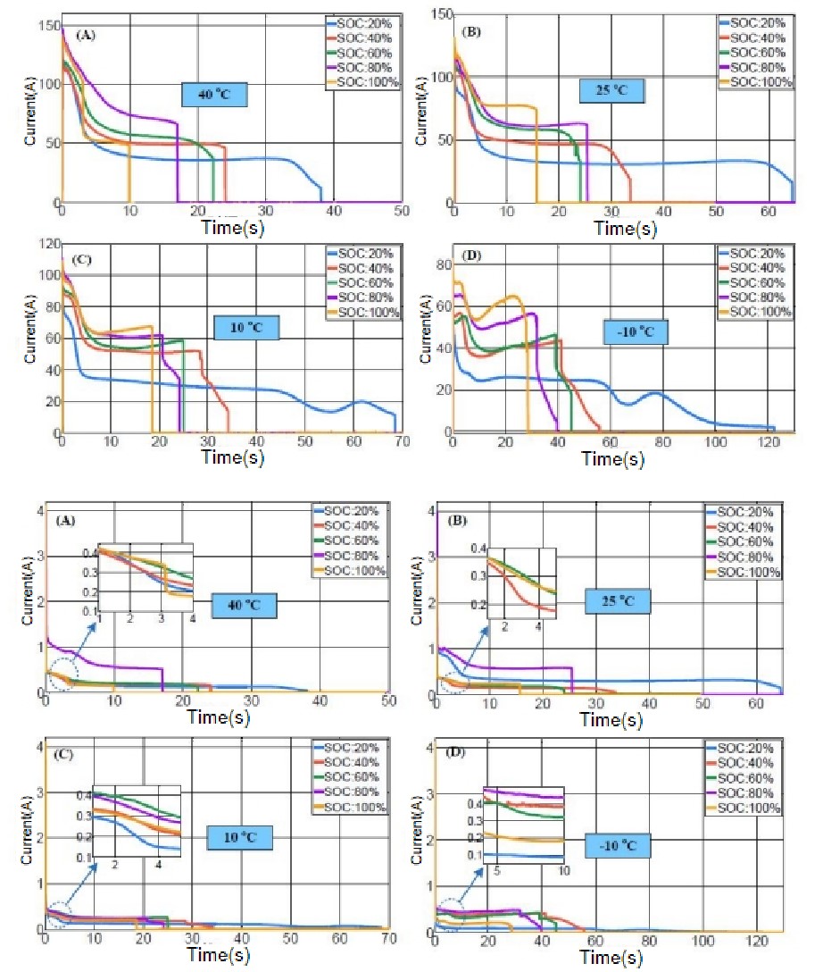
Fig. 3 External short-circuit test currents and voltages for cells with initial SOC of 20%, 40%, 60%, 80%, and 100% Results: (A) at 40°C; (B) at 25°C; (C) at 10°C; (D) -10°C
The evaluation criteria for short-circuit testing include the following: First, the test needs to simulate the short-circuit situation of the battery in the actual use environment to ensure the authenticity and reliability of the test results. This usually includes short-circuit testing under different temperatures, humidity and vibration conditions to comprehensively assess the battery's performance in various possible actual use environments. Next, the battery's current and voltage changes during short-circuit are evaluated, and the peak current and duration are recorded to determine the battery's short-circuit tolerance. This process requires high-precision test equipment to capture transient current and voltage changes, and to evaluate the battery's electrical performance by analyzing these data.
At the same time, the temperature change of the battery during the short-circuit process is observed to assess its thermal stability. Thermal imaging devices or embedded temperature sensors can be used to monitor the temperature distribution and changes of the battery to ensure that the battery does not overheat due to short-circuiting and lead to thermal runaway. In addition, detecting whether the battery has suffered a safety incident such as fire, explosion or leakage to assess its safety performance. Any form of battery case breakage, gas release, spark or flame generation is a serious safety issue that must be documented and analyzed in detail during testing.
It is also necessary to assess the battery's resilience after a short circuit, i.e., whether the battery can return to its normal function after experiencing a short circuit, or the extent of its performance degradation. This process involves re-testing and evaluating the battery's capacity, internal resistance, cycle life and other key parameters. By comparing the performance of different batteries under the same short-circuit conditions, the strengths and weaknesses of the battery design and manufacturing process can be evaluated, possible design flaws or process problems can be identified, and recommendations for improvement can be made.
Finally, the results of the short-circuit test need to be compared with relevant industry standards and regulations, such as UN38.3, UL1642 and IEC62133, to ensure that the battery products comply with international safety standards and regulatory requirements. These standards specify in detail the conditions, methods and evaluation indexes of short-circuit test, which is an important basis for evaluating the safety and reliability of batteries. Through comprehensive short-circuit testing, we can ensure the safety and reliability of batteries in a variety of use environments, providing important feedback and improvement direction for battery design and manufacturing.
Understanding the formation mechanism and test methods of internal and external short circuits in lithium-ion batteries is crucial for the safety enhancement in battery design, manufacturing and use. By improving battery materials, optimizing the manufacturing process, strengthening quality testing, and taking protective measures during use, the occurrence of internal and external short circuits can be effectively reduced, and the safety performance and reliability of the battery can be enhanced.


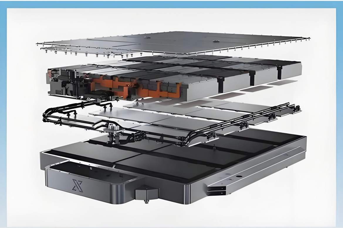


Technology
December 04, 2025
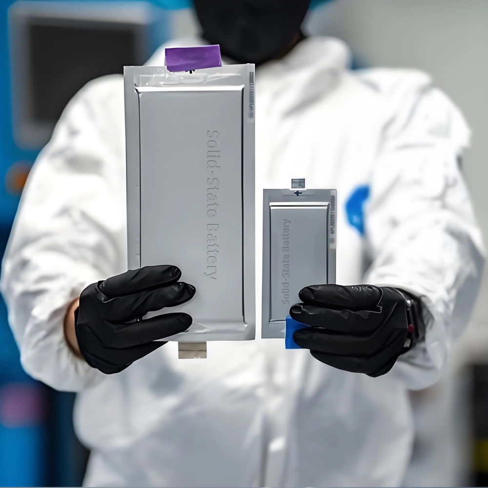
The lab focuses on solid-state battery research to overcome traditional lithium batteries' safety and energy density issues, supporting environmental sustainability. It develops innovative solid-state electrolytes, refines electrode materials, and investigates ion transfer and interface stability to revolutionize battery technology.

The electric vehicle battery industry is rapidly developing, focusing on technological innovation, market competition, and sustainability. Research hotspots include solid-state batteries, new types of electrolytes, BMS optimization, and recycling technologies. The environmental adaptability, safety, and economic viability of batteries are key research areas, and the industry is expected to undergo more innovation and transformation.
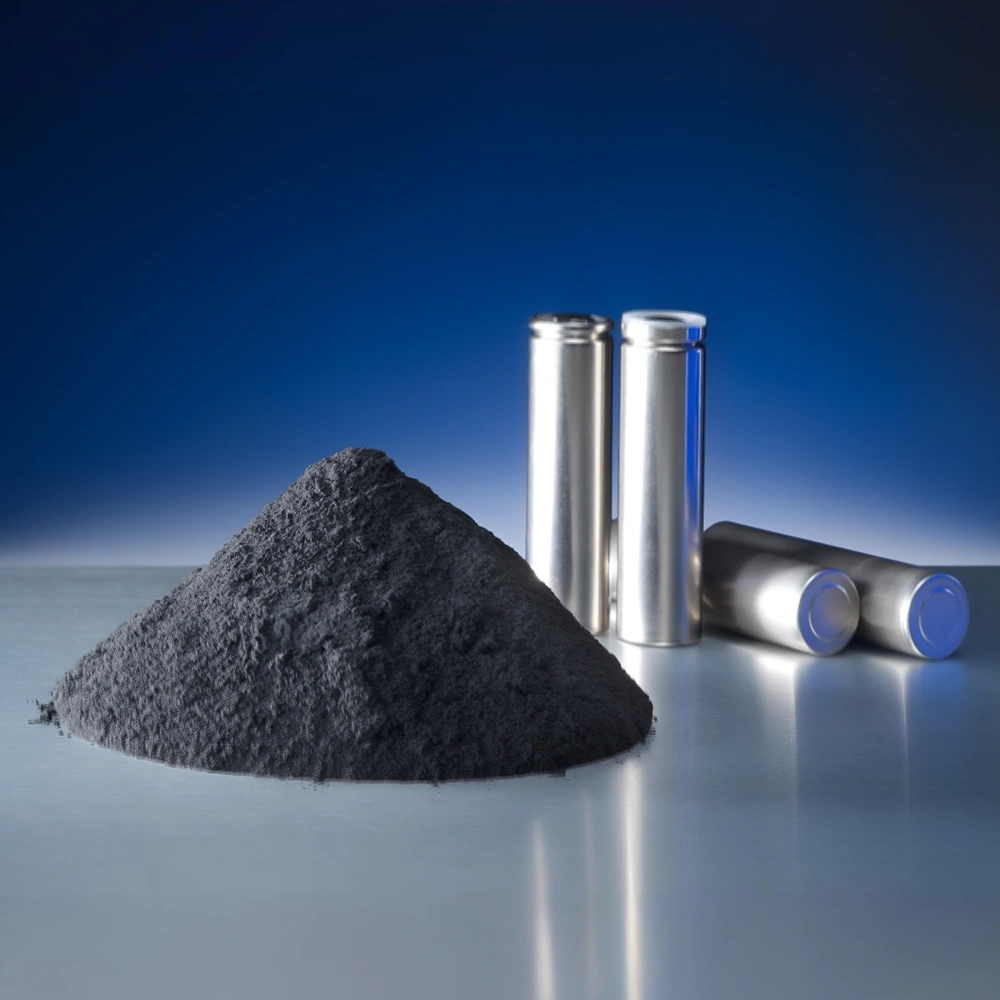
We specialize in battery preparation technology research, focusing on overcoming existing energy storage challenges by innovating in electrode materials, battery chemistry, and manufacturing processes to improve performance, enhance safety, and reduce costs. Sustainability and recycling technologies for batteries are also emphasized to mitigate environmental impacts and foster the growth of green energy.