Part 1 Hardware connection
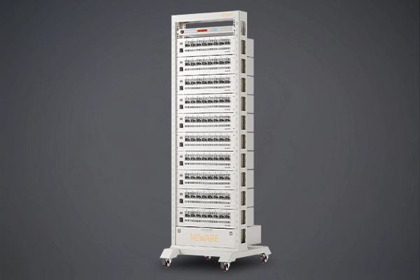
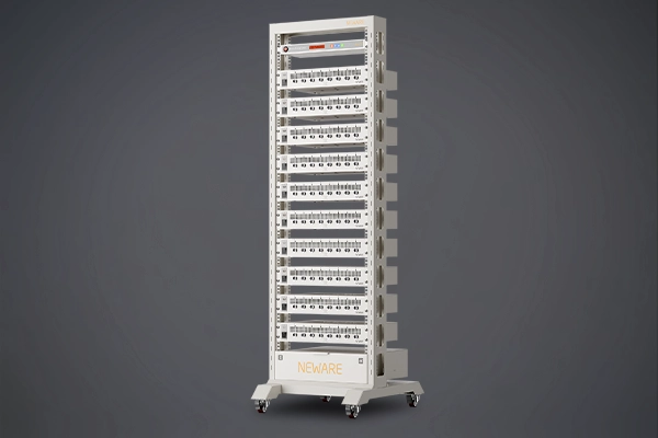
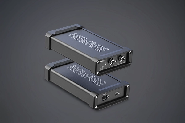
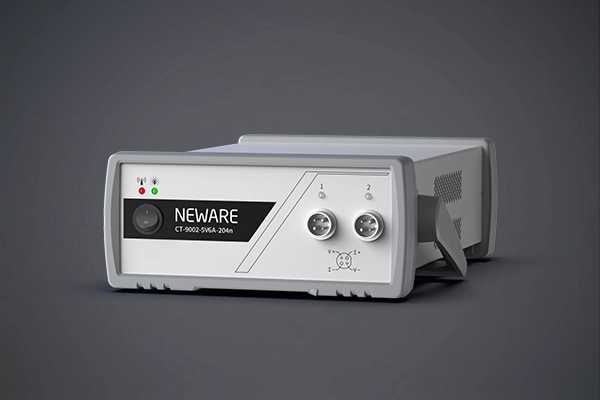
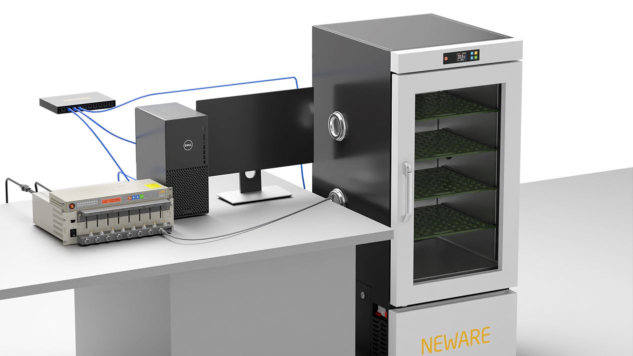
The computer is connected to the switch through a network cable, and the switch is connected to the Control unit and the Temperature Chamber respectively through a network cable.
Part 2 Control unit and the Temperature Chamber mode configuration
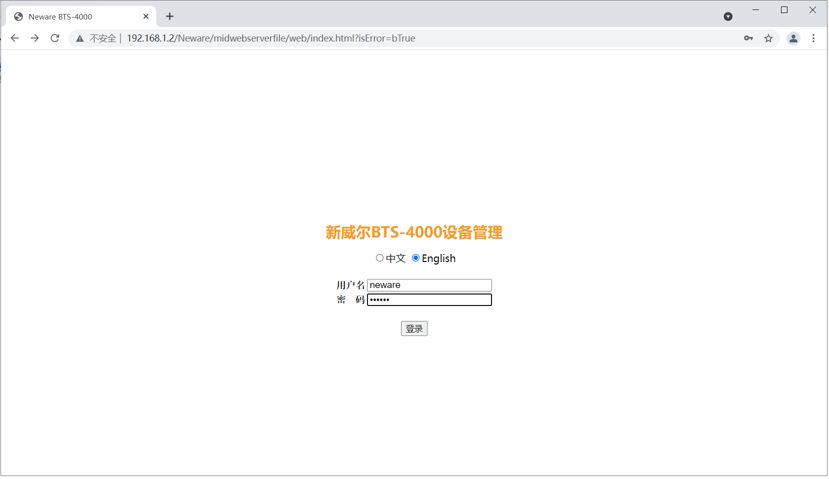
1. Enter the IP of the Control unit in the browser to log in to the NEWARE device management page (user name: neware; password: xinwei), the IP of the Control unit can be viewed in the device body tab.
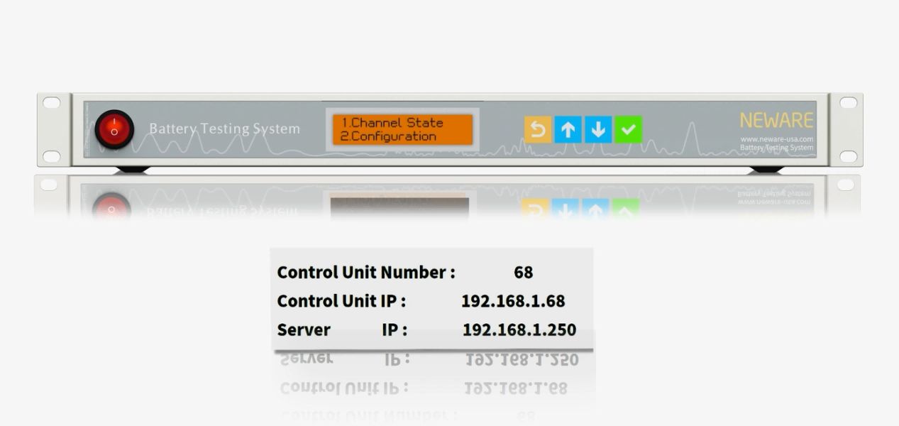
(The IP in the picture is for demonstration only, please refer to the actual equipment)
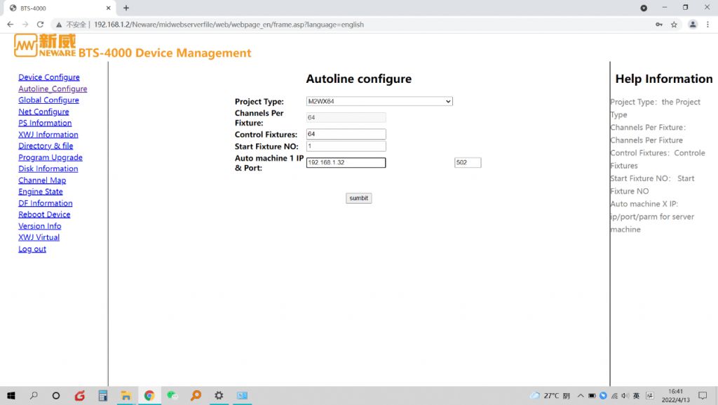
2. Select Project Type Configuration, select M2WX64 for Project Type, the IP address of the automation device is the IP address set on the chamber and the port number is on the right side, the settings are consistent with the chamber, click submit after the settings are completed (the chamber needs to change the IP address and the port number in the shutdown state). The operation interface is shown in the figure below.
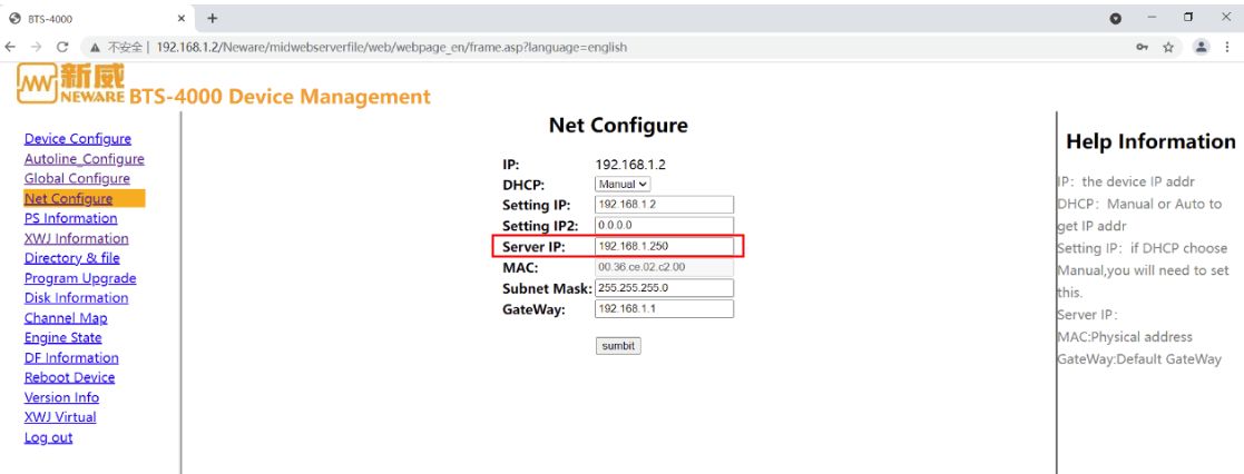
3. Server IP and device IP configuration
The server IP is the operating computer, and the setting interface is shown below.
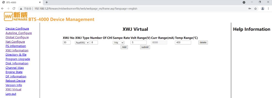
4. Add virtual auxiliary channel.
The temperature module needs auxiliary channel to display, if there is no physical auxiliary lower unit, you need to add virtual auxiliary lower unit in the web interface of the central station, this setting is limited to M2 temperature chamber.
Caution:
Do not conflict with the physical device number, set it and submit it.
Virtual devices are also counted as device number, which will affect the neutralizer frequency after exceeding the corresponding device number.
After the configuration is completed click Submit and refresh it to make sure whether the setting is successful or not and then reboot. Reboot the Control unit by entering the user name and password and clicking Reboot, as shown in the following figure.
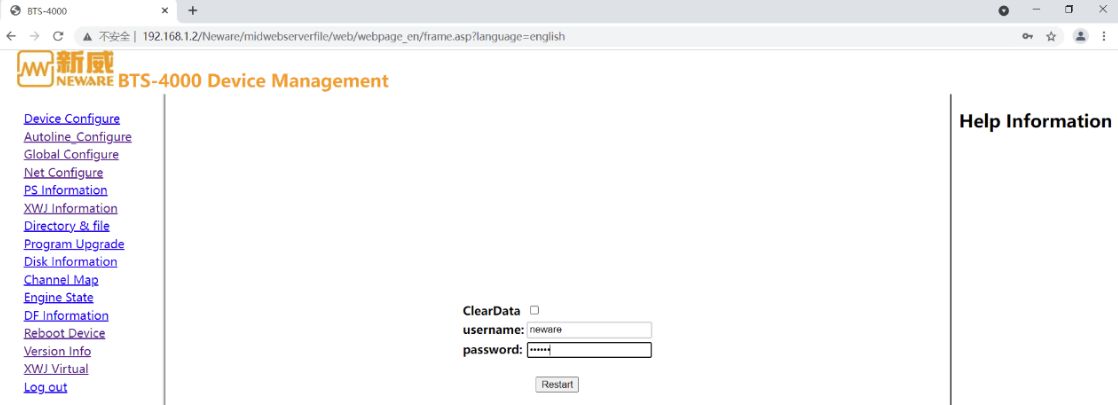
After rebooting, the device information appears as "XWJ_NO 30", and the control unit is successfully connected to the Temperature Chamber.

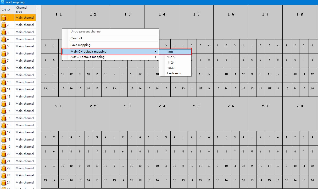
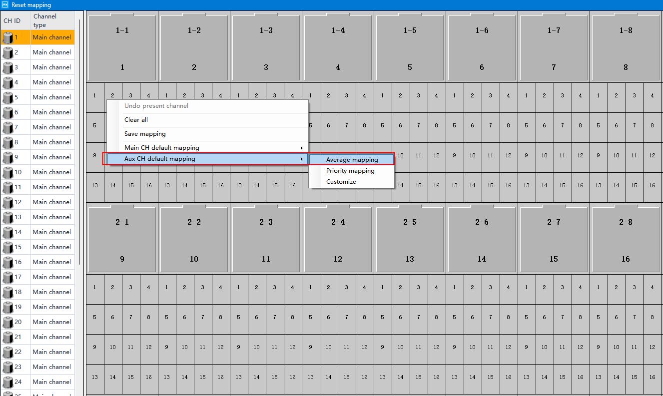
5. Client mapping channels.
Right-click and select “Reset mappings”, then right-click and select “Main CH default mapping-1 x 8”.
Continue to right-click and select “Aux CH default mapping - Average mapping”.
6. To set the warm box mode.
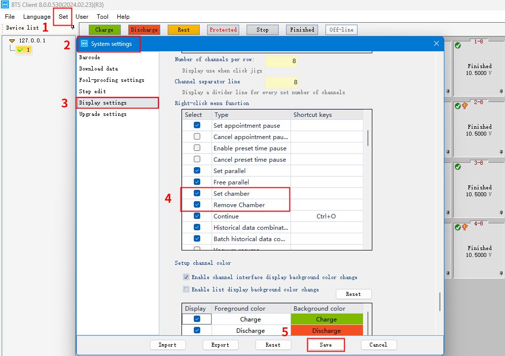
Click Set → System settings → Display settings → Find “Set chamber” and “Remove chamber” in “Right-click menu function”.
Save the setting.
7. Temperature Chamber
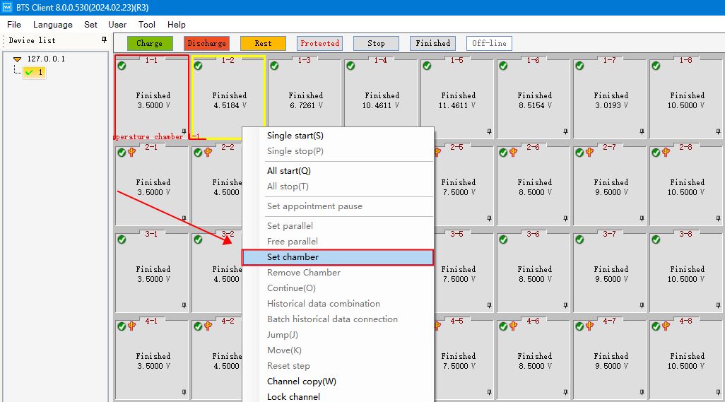
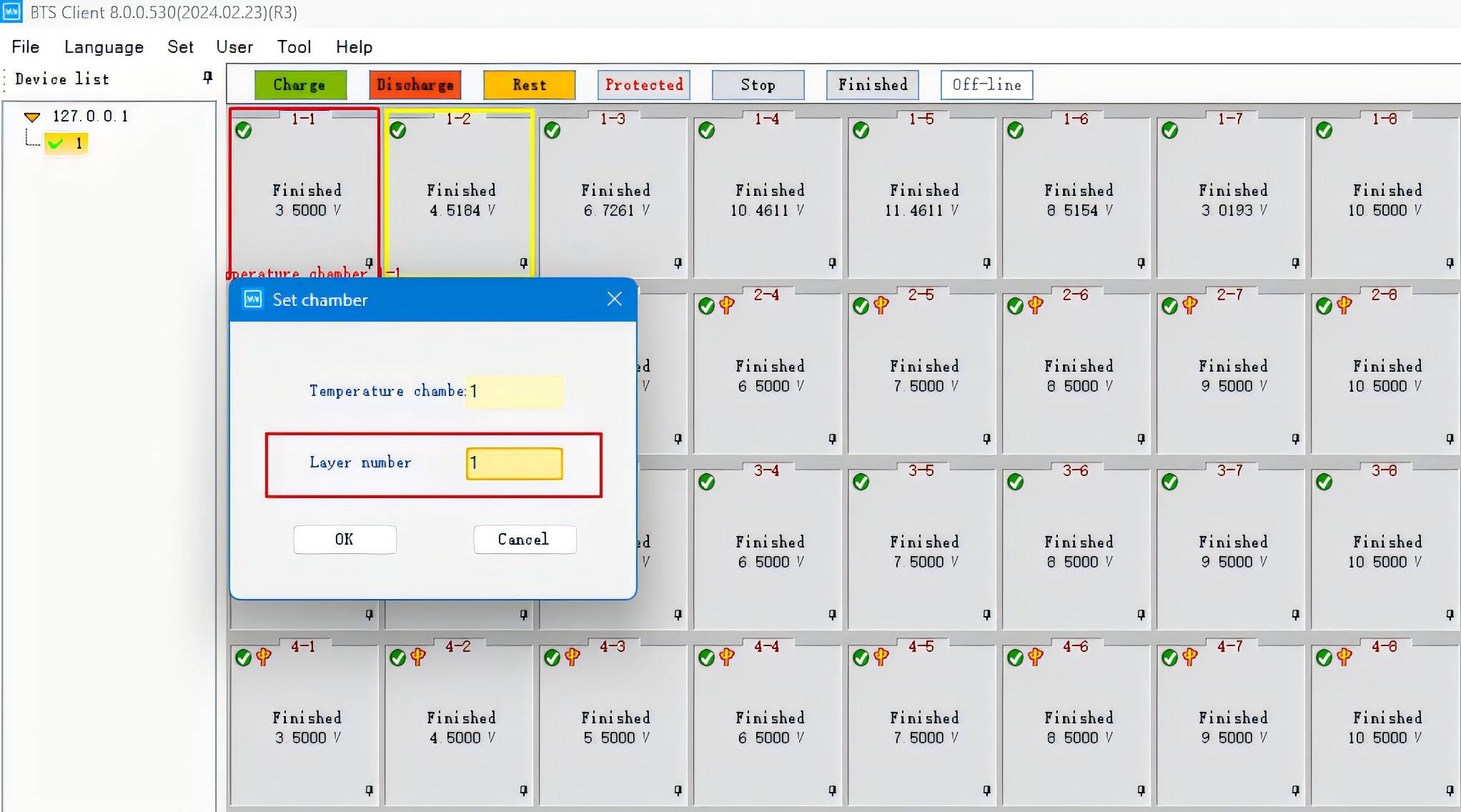
Select the channel, right click “Set chamber” (Since a work step test is required, you need to select the channel of the battery that is placed in the Chamber. You can set up only one channel for the control box alone, so just select it according to your needs.)
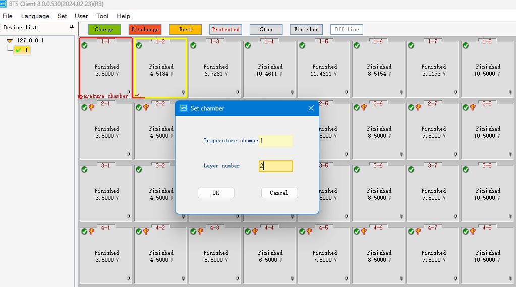
Set the temperature box number and layer number, and then click Confirm to display the set “Temperature chamber 1-2”.
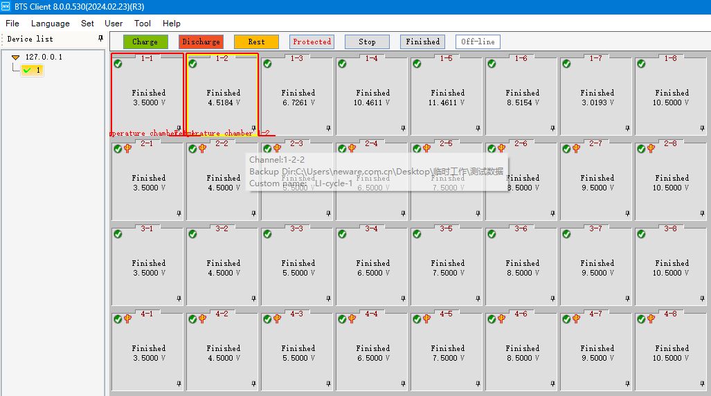
8. Introduction to the operation of the simple temperature box
After the setting is completed, start the corresponding channel step, select “Control” and set “Temperature control ”.
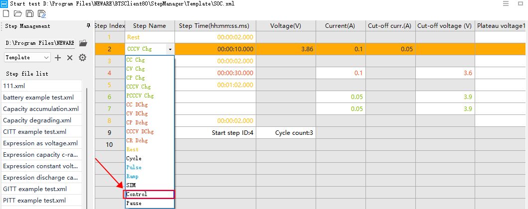

To control work step jumping, you need to add an if condition in “Other” to jump to other work steps by yourself.

Part 3 FAQs
1. Network cable connection error: the network cable of the Temperature Chamber must be connected to the switch.
2. The neutralizer from version 4S_2.12.7.4_20201117_135042, when setting up the warm box, the layer number can only be 1.
3. IP error
Constant Temperature Chamber and All-in-One Testing System can change IP on the screen by hand, high and low temperature box in the screen is not display IP;
The original IP of the high/low temperature box is 192.168.1.80 or 192.168.1.100.

